There are lots of things in
market that need to work with Gyroscope Sensor like Smartphone, Fitbit (Smart
Watches), Smart Headset, Gaming Devices, Drone, UAV’s, Flight Controller and
etc. With MPU6050 module, we can work and refer with gyroscope and
accelerometer sensing using Arduino Boards just some wiring and coding.
In this post, we will learn about how does it work and how to interface
with Arduino Boards which follows –
>>What is MPU6050
Sensor?
>>Parts Required
>>Circuit Diagram
>>Libraries and Coding
>>Reading value from
sensor
>>Processing 3D
Visualizer
What is MPU6050 Sensor?
Parts Required
Arduino Uno or Nano
MPU6050 Sensor
Jumper Wires
Breadboard
USB Cable
Circuit Diagram
The MPU6050 Module only
supports I2C Communication I already mentioned before.
The first sensor Pin (VCC) is
connect with Arduino VCC (5V) Pin.
The second pin of senor (GND)
is connect with Arduino GND pin.
The third pin of sensor (SCL)
is connect with Arduino Analog A5 pin.
The fourth pin of sensor (SDA)
is connect with Arduino Analog A4 pin.
And the last pin of Sensor
(INT) is connect with Arduino Digital D2 pin.
Note: XDA, XCL, ADO pins are
not required for some projects and electronics very rare use of these pins for
Arduino.
Libraries and Coding
Before uploading any code we
need to download two libraries first one is I2C Device download from here and
the second one is MPU6050 is here and after download, open the Arduino IDE
Software in the Sketch menu click on
the Include Library and then click Add .Zip Library here upload Library
where you downloaded or save the both .zip libraries.
If you have done correctly
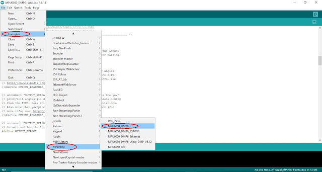
then open MPU6050_DMP Example in File menu’s Example section and here you can find MPU6050 just click on it.
Here in this code need to
change two lines first one is
#define
OUTPUT_READABLE_YAWPITCHROLL to comment it by two slash
//#define
OUTPUT_READABLE_YAWPITCHROLL and second is
//#define OUTPUT_TEAPOT to uncomment it by #define
OUTPUT_TEAPOT
Then check the Board and Port and Upload it to Arduino Nano
or Uno.
Processing 3D Visualizer
For 3D Simulation in Processing Software if don’t have first
of all process you have to download from here again you need to download two
libraries first one is Toxiclibs_p5 and second is Toxiclibscore Compressed in
teapotlib.zip Library after downloading this file unzip it and copy both folder
and paste in Processing Libraries Folder here in my case C:\Users\hp\Documents\Processing\libraries
just paste on it.
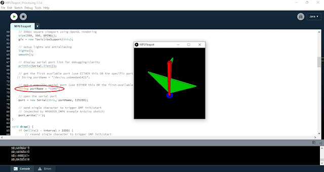
Now Open Processing IDE then copy this code and paste in
Processing Software and here in line 74 change the Port of your Board like this
String portName = "COM4";
Code for Processing
// I2C device class (I2Cdev) demonstration Processing sketch for MPU6050 DMP output
// 6/20/2012 by Jeff Rowberg <jeff@rowberg.net>
// Updates should (hopefully) always be available at https://github.com/jrowberg/i2cdevlib
//
// Changelog:
//     2012-06-20 - initial release

/* ============================================
I2Cdev device library code is placed under the MIT license
Copyright (c) 2012 Jeff Rowberg

Permission is hereby granted, free of charge, to any person obtaining a copy
of this software and associated documentation files (the "Software"), to deal
in the Software without restriction, including without limitation the rights
to use, copy, modify, merge, publish, distribute, sublicense, and/or sell
copies of the Software, and to permit persons to whom the Software is
furnished to do so, subject to the following conditions:

The above copyright notice and this permission notice shall be included in
all copies or substantial portions of the Software.

THE SOFTWARE IS PROVIDED "AS IS", WITHOUT WARRANTY OF ANY KIND, EXPRESS OR
IMPLIED, INCLUDING BUT NOT LIMITED TO THE WARRANTIES OF MERCHANTABILITY,
FITNESS FOR A PARTICULAR PURPOSE AND NONINFRINGEMENT. IN NO EVENT SHALL THE
AUTHORS OR COPYRIGHT HOLDERS BE LIABLE FOR ANY CLAIM, DAMAGES OR OTHER
LIABILITY, WHETHER IN AN ACTION OF CONTRACT, TORT OR OTHERWISE, ARISING FROM,
OUT OF OR IN CONNECTION WITH THE SOFTWARE OR THE USE OR OTHER DEALINGS IN
THE SOFTWARE.
===============================================
*/

import processing.serial.*;
import processing.opengl.*;
import toxi.geom.*;
import toxi.processing.*;

// NOTE: requires ToxicLibs to be installed in order to run properly.
// 1. Download from http://toxiclibs.org/downloads
// 2. Extract into [userdir]/Processing/libraries
//    (location may be different on Mac/Linux)
// 3. Run and bask in awesomeness

ToxiclibsSupport gfx;

Serial port;                         // The serial port
char[] teapotPacket = new char[14];  // InvenSense Teapot packet
int serialCount = 0;                 // current packet byte position
int aligned = 0;
int interval = 0;

float[] q = new float[4];
Quaternion quat = new Quaternion(1, 0, 0, 0);

float[] gravity = new float[3];
float[] euler = new float[3];
float[] ypr = new float[3];

void setup() {
    // 300px square viewport using OpenGL rendering
    size(300, 300, OPENGL);
    gfx = new ToxiclibsSupport(this);

    // setup lights and antialiasing
    lights();
    smooth();

    // display serial port list for debugging/clarity
    println(Serial.list());

    // get the first available port (use EITHER this OR the specific port code below)
   // String portName = "/dev/cu.usbmodem1421";

    // get a specific serial port (use EITHER this OR the first-available code above)
    String portName = "COM3";

    // open the serial port
    port = new Serial(this, portName, 38400);

    // send single character to trigger DMP init/start
    // (expected by MPU6050_DMP6 example Arduino sketch)
    port.write('r');
}

void draw() {
    if (millis() - interval > 1000) {
        // resend single character to trigger DMP init/start
        // in case the MPU is halted/reset while applet is running
        port.write('r');
        interval = millis();
    }

    // black background
    background(0);

    // translate everything to the middle of the viewport
    pushMatrix();
    translate(width / 2, height / 2);

    // 3-step rotation from yaw/pitch/roll angles (gimbal lock!)
    // ...and other weirdness I haven't figured out yet
    //rotateY(-ypr[0]);
    //rotateZ(-ypr[1]);
    //rotateX(-ypr[2]);

    // toxiclibs direct angle/axis rotation from quaternion (NO gimbal lock!)
    // (axis order [1, 3, 2] and inversion [-1, +1, +1] is a consequence of
    // different coordinate system orientation assumptions between Processing
    // and InvenSense DMP)
    float[] axis = quat.toAxisAngle();
    rotate(axis[0], -axis[1], axis[3], axis[2]);

    // draw main body in red
    fill(255, 0, 0, 200);
    box(10, 10, 200);

    // draw front-facing tip in blue
    fill(0, 0, 255, 200);
    pushMatrix();
    translate(0, 0, -120);
    rotateX(PI/2);
    drawCylinder(0, 20, 20, 8);
    popMatrix();

    // draw wings and tail fin in green
    fill(0, 255, 0, 200);
    beginShape(TRIANGLES);
    vertex(-100,  2, 30); vertex(0,  2, -80); vertex(100,  2, 30);  // wing top layer
    vertex(-100, -2, 30); vertex(0, -2, -80); vertex(100, -2, 30);  // wing bottom layer
    vertex(-2, 0, 98); vertex(-2, -30, 98); vertex(-2, 0, 70);  // tail left layer
    vertex( 2, 0, 98); vertex( 2, -30, 98); vertex( 2, 0, 70);  // tail right layer
    endShape();
    beginShape(QUADS);
    vertex(-100, 2, 30); vertex(-100, -2, 30); vertex(  0, -2, -80); vertex(  0, 2, -80);
    vertex( 100, 2, 30); vertex( 100, -2, 30); vertex(  0, -2, -80); vertex(  0, 2, -80);
    vertex(-100, 2, 30); vertex(-100, -2, 30); vertex(100, -2,  30); vertex(100, 2,  30);
    vertex(-2,   0, 98); vertex(2,   0, 98); vertex(2, -30, 98); vertex(-2, -30, 98);
    vertex(-2,   0, 98); vertex(2,   0, 98); vertex(2,   0, 70); vertex(-2,   0, 70);
    vertex(-2, -30, 98); vertex(2, -30, 98); vertex(2,   0, 70); vertex(-2,   0, 70);
    endShape();

    popMatrix();
}

void serialEvent(Serial port) {
    interval = millis();
    while (port.available() > 0) {
        int ch = port.read();
        print((char)ch);
        if (ch == '$') {serialCount = 0;} // this will help with alignment
        if (aligned < 4) {
            // make sure we are properly aligned on a 14-byte packet
            if (serialCount == 0) {
                if (ch == '$') aligned++; else aligned = 0;
            } else if (serialCount == 1) {
                if (ch == 2) aligned++; else aligned = 0;
            } else if (serialCount == 12) {
                if (ch == '\r') aligned++; else aligned = 0;
            } else if (serialCount == 13) {
                if (ch == '\n') aligned++; else aligned = 0;
            }
            //println(ch + " " + aligned + " " + serialCount);
            serialCount++;
            if (serialCount == 14) serialCount = 0;
        } else {
            if (serialCount > 0 || ch == '$') {
                teapotPacket[serialCount++] = (char)ch;
                if (serialCount == 14) {
                    serialCount = 0; // restart packet byte position

                    // get quaternion from data packet
                    q[0] = ((teapotPacket[2] << 8) | teapotPacket[3]) / 16384.0f;
                    q[1] = ((teapotPacket[4] << 8) | teapotPacket[5]) / 16384.0f;
                    q[2] = ((teapotPacket[6] << 8) | teapotPacket[7]) / 16384.0f;
                    q[3] = ((teapotPacket[8] << 8) | teapotPacket[9]) / 16384.0f;
                    for (int i = 0; i < 4; i++) if (q[i] >= 2) q[i] = -4 + q[i];

                    // set our toxilibs quaternion to new data
                    quat.set(q[0], q[1], q[2], q[3]);

                    /*
                    // below calculations unnecessary for orientation only using toxilibs

                    // calculate gravity vector
                    gravity[0] = 2 * (q[1]*q[3] - q[0]*q[2]);
                    gravity[1] = 2 * (q[0]*q[1] + q[2]*q[3]);
                    gravity[2] = q[0]*q[0] - q[1]*q[1] - q[2]*q[2] + q[3]*q[3];

                    // calculate Euler angles
                    euler[0] = atan2(2*q[1]*q[2] - 2*q[0]*q[3], 2*q[0]*q[0] + 2*q[1]*q[1] - 1);
                    euler[1] = -asin(2*q[1]*q[3] + 2*q[0]*q[2]);
                    euler[2] = atan2(2*q[2]*q[3] - 2*q[0]*q[1], 2*q[0]*q[0] + 2*q[3]*q[3] - 1);

                    // calculate yaw/pitch/roll angles
                    ypr[0] = atan2(2*q[1]*q[2] - 2*q[0]*q[3], 2*q[0]*q[0] + 2*q[1]*q[1] - 1);
                    ypr[1] = atan(gravity[0] / sqrt(gravity[1]*gravity[1] + gravity[2]*gravity[2]));
                    ypr[2] = atan(gravity[1] / sqrt(gravity[0]*gravity[0] + gravity[2]*gravity[2]));

                    // output various components for debugging
                    //println("q:\t" + round(q[0]*100.0f)/100.0f + "\t" + round(q[1]*100.0f)/100.0f + "\t" + round(q[2]*100.0f)/100.0f + "\t" + round(q[3]*100.0f)/100.0f);
                    //println("euler:\t" + euler[0]*180.0f/PI + "\t" + euler[1]*180.0f/PI + "\t" + euler[2]*180.0f/PI);
                    //println("ypr:\t" + ypr[0]*180.0f/PI + "\t" + ypr[1]*180.0f/PI + "\t" + ypr[2]*180.0f/PI);
                    */
                }
            }
        }
    }
}

void drawCylinder(float topRadius, float bottomRadius, float tall, int sides) {
    float angle = 0;
    float angleIncrement = TWO_PI / sides;
    beginShape(QUAD_STRIP);
    for (int i = 0; i < sides + 1; ++i) {
        vertex(topRadius*cos(angle), 0, topRadius*sin(angle));
        vertex(bottomRadius*cos(angle), tall, bottomRadius*sin(angle));
        angle += angleIncrement;
    }
    endShape();

    // If it is not a cone, draw the circular top cap
    if (topRadius != 0) {
        angle = 0;
        beginShape(TRIANGLE_FAN);

        // Center point
        vertex(0, 0, 0);
        for (int i = 0; i < sides + 1; i++) {
            vertex(topRadius * cos(angle), 0, topRadius * sin(angle));
            angle += angleIncrement;
        }
        endShape();
    }

    // If it is not a cone, draw the circular bottom cap
    if (bottomRadius != 0) {
        angle = 0;
        beginShape(TRIANGLE_FAN);

        // Center point
        vertex(0, tall, 0);
        for (int i = 0; i < sides + 1; i++) {
            vertex(bottomRadius * cos(angle), tall, bottomRadius * sin(angle));
            angle += angleIncrement;
        }
        endShape();
    }
}
Now run the code after all setup has been done if any problem
check the code you have uploaded in Arduino or Check the all connection in
circuit it will take few second for initializing the sensor.


Comments
Post a Comment